
Novel in-core crack growth test conducted at the MIT Reactor
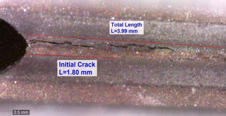
Post-irradiation picture of the crack
A key component in evaluating the ability of nuclear reactors to operate beyond 60 years is characterizing the degradation of materials exposed to radiation and various water chemistries. Of particular concern is the response of reactor materials to a combination of stress, irradiation, and chemistry that leads to crack growth, also known as Irradiation-Assisted Stress Corrosion Cracking (IASCC). Techniques to measure crack growth in high-temperature water and with in-core radiation levels have previously been developed at some test reactors outside the United States. Now, an in-core crack growth test has been conducted in full light water reactor conditions (10.3 MPa and 298°C) at the MIT Nuclear Reactor Laboratory (NRL).
This US Department of Energy-funded collaborative project between the Idaho National Laboratory and the MIT-NRL began in 2012. The goal was to develop the equipment and techniques necessary to conduct in-pile IASCC tests in current U.S. Materials Testing Reactors (MTRs).
The project designed and tested a loader mechanism, electronic support equipment, and an autoclave for the experiment capable of being used in the MIT Reactor (MITR). Cyclical loads were applied to a 1/4 scale Compact Tension (CT) specimen by means of a scissor-like mechanism, actuated by a high-pressure, miniature gas bellows. Crack growth was measured using the Direct Current Potential Drop (DCPD) method. A schematic and photograph of the loading and DCPD components are shown below.
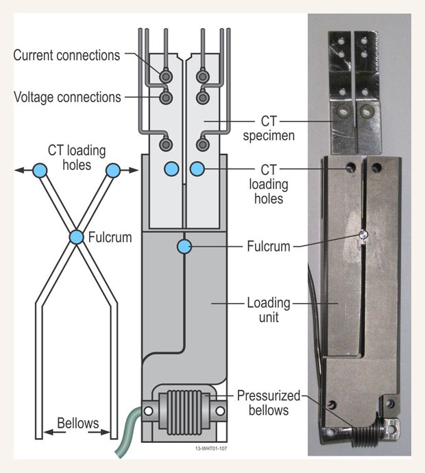
Loading and DCPD components (figure and photo by Joe Palmer, INL)
Successful operation of the test rig was demonstrated with the specimen cycled more than 8000 times which propagated a crack of over 2 mm. Post-irradiation examination of the specimen in a hot cell at the MIT NRL confirmed a crack length within 5% of that inferred during the in-core test.
Challenges and Solutions
The experiment faced a range of mechanical challenges to overcome in the system’s design. First, the mechanical components of the system need to be miniaturized to fit within the available high-temperature, high-pressure experimental position in the MITR core (the space has a diameter of about 3.87 cm). Selection, integration, and testing of small high-pressure, high-temperature bellows that would survive a sufficient number of pressure cycles also required extensive efforts. The final loader mechanism was constructed of a 6Al-4V titanium alloy; the bellows were made of aged Inconel® 718 with end fittings and the gas supply tube attached by laser welding. The length of the loading unit (shown above) is about 9.5 cm.
Electro-mechanical design issues included selecting and developing robust current and voltage leads and connections, and selecting appropriate ceramic insulating materials that could endure the reactor environment. To achieve reliable electrical connections, the cables were welded to a large boss that was welded to the specimen. The specimen was electrically isolated from the loading mechanism by high-purity alumina bushings.
Systems were also developed to address nuclear-related electrical signal issues such as electromagnetic noise caused by free beta particles and electrons, thermocouple effects due to by localized nuclear heating, and nuclear-induced material property changes that affected the specimen’s electrical resistance as the experiment progressed. The DC current to the specimen was reversed regularly to correct for thermocouple effects. Potential drop across the specimen was measured by a nanovolt meter that averaged hundreds or thousands of individual readings, and the voltage drop along each leg of the CT specimen was used to compensate for resistance change in the specimen unrelated to the crack growth.
The Test
Various initial performance checks were performed to ensure that the high-pressure gas system, current supplies and switching, electronic signal processing, and safety alarms and responses functioned as planned. The system was then brought up to the test temperature of 298°C, the reactor was brought to power, and the full cyclical loading of the specimen began. The system was run in a variety of conditions for a total of 67 days. DCPD readings were recorded continuously to examine the effects of different loadings and radiation levels on the voltage drop across the specimen. Using a relationship between the DCPD readings and crack growth determined in out-of-core tests at the Idaho national laboratory (INL), the final crack growth extension for the test was estimated to be 2.09 mm.
After the irradiation, the full test rig was transferred intact from the reactor core into the MITR hot cell to enable a direct measurement of the crack length. The loader was placed in a fixture holding a calibrated digital microscope. The bellows was pressurized to fully open the crack for a clear micro-photo (shown below) which enabled the full the crack length to be measured as 3.99 mm. Subtracting the pre-test crack length of 1.8 mm yielded an in-reactor crack extension of 2.19 mm that compares very well with the DCPD inferred crack growth of 2.09 mm.
Overall, the INL / MIT-NRL team designed, developed, and demonstrated the first system in the U.S. that can perform real-time high-temperature, aqueous, crack growth tests in the core of a research reactor. This system can now be applied to the analysis of irradiation assisted stress corrosion cracking and the assessment of material degradation in nuclear reactors.
This research will be presented at the American Nuclear Society’s next International Congress on Advances in Nuclear Power Plants (ICAPP, San Francisco, USA, April 17-20, 2016) as “Adaptation of Crack Growth Detection Techniques to US Material Test Reactors”, A.J. Palmer, S.P. Teysseyre, K.L. Davis, (Idaho National Laboratory); G. Kohse, Y. Ostrovsky, D.M. Carpenter (Massachusetts Institute of Technology); J.L. Rempe (Rempe and Associates, LLC).